|
|
The successful delivery of a packet over a NetWare network depends on the proper addressing of the packet. To send a packet, the sender must know the full IPX address (network, node, and socket) of the recipient. The address is specified in the packet's medium-access protocol and IPX protocol address fields. Once the sender has the recipient's address, it can address the packet. The way the MAC header of that packet is addressed, however, depends on the network's topography. Specifically, it depends on whether the sending node and the destination node are separated by a router. The effect of network topography on IPX addressing is discussed in the following sections.
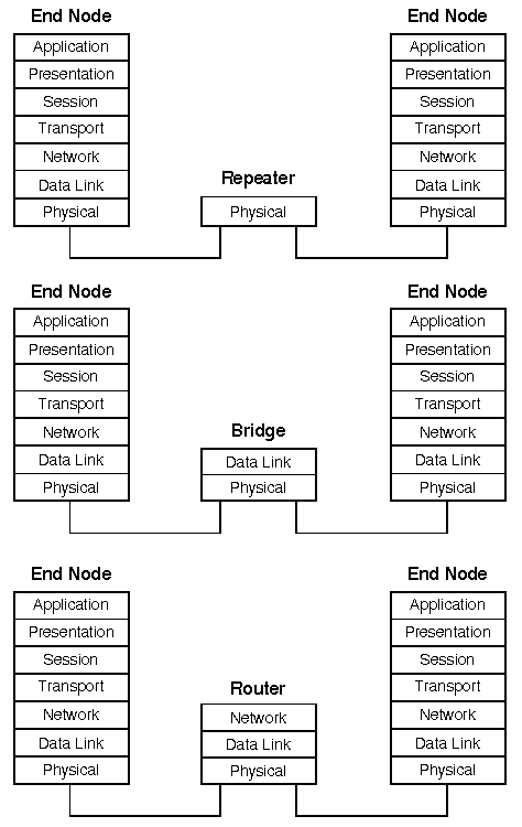
Segments on a network can be interconnected using a:

OSI Representations of Network Devices
A repeater is a physical layer (OSI model) device that amplifies the signal of one segment onto one or more other segments. Repeaters are used to extend the maximum possible distance between end nodes on a segment. They are completely transparent to the sending and receiving nodes.
A bridge is a data link layer device used to interconnect cable segments locally or over wide area network links. Instead of simply amplifying a signal as repeaters do, bridges retransmit packets received on one segment onto another segment. Bridges are considered data link layer devices because they examine the data link (or MAC header) portion of packets before retransmitting them onto other segments. There are two predominant types of bridge:
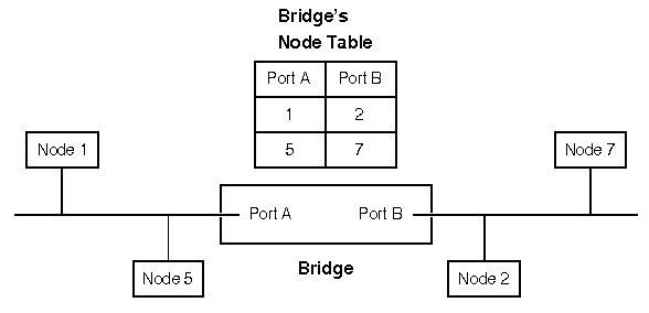
Sample Transparent Bridge
After examining the packets transmitted on both segments, the bridge creates a table that tracks which nodes exist on each segment. With this table, the bridge can filter unnecessary traffic. For instance, if node 1 sends a packet to node 5, the bridge will not retransmit that packet on its port B. It will, however, retransmit packets sent from node 1 to node 7. Like repeaters, transparent bridges -- as their name implies -- are transparent to the sending and receiving nodes.
Routers interconnect different network segments. However, unlike bridges, routers, by definition, are network layer devices (see ``OSI Representations of Network Devices''). In other words, routers receive their instructions for forwarding a packet from one segment to another from a network layer protocol.
NetWare-compatible routers are available with NetWare or from third-party manufacturers. The routers that come packaged with NetWare have actually been misnamed ``bridges'' in the past. The NetWare routers include what has been called the internal bridge within NetWare file servers and the external bridge installed at workstations. Novell has officially renamed these two devices ``internal router'' and ``external router''.
NetWare-compatible routers can be configured to interconnect two or more segments. Each of these segments, however, must be assigned a unique network number to distinguish it from other segments on the network. A segment's network number must be configured into each of the routers connected to that segment. The network number serves as a common address for each node connected to a segment. For more information on assigning a segment's network number, see ``Configuration parameters''.
If the sending node and the destination node are on the same network segment -- that is, they both have the same IPX network number -- the sending node addresses the packet in the following way:
``Transmission to Same Network Segment (No Routing Required)'' shows an example of two nodes that are connected to network number AA.
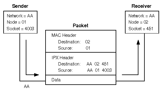
Transmission to Same Network Segment (No Routing Required)
The sending node (node 01) sends a packet to node 02. The sending node places node number 02 in the destination field and node number 01 in the source field of the MAC. In the destination address fields of the IPX header, the sending node places AA, 02, and 451 (the full IPX address of the receiving node). The sending node places its own IPX address of AA, 01, and 4003 in the source address fields of the IPX header.
The addressing method depicted in ``Transmission to Same Network Segment (No Routing Required)'' is used when the two nodes reside on the same physical segment (or ring) or if they reside on separate segments interconnected by repeaters or bridges.
If the two nodes have different network numbers (reside on different network segments), the sending node must find a router on its own segment that can forward packets to the destination node's network segment. To find this router, the workstation broadcasts a RIP packet requesting the fastest route to the destination node's network number. This RIP request is responded to by the router residing on the sending node's segment with the shortest path to the desired segment; in the response, the router includes its node number.
Once the sending node receives the router's node number, it is prepared to send packets to the destination node. The sending node addresses these packets by placing:
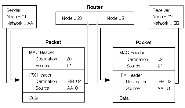
Packet addressing through a router
When a router receives a packet to be routed, it can take one of two possible actions. If the packet is destined for a network number to which the router is directly connected, the router will:
To forward packets by the best possible route, NetWare routers maintain a routing information table that holds information about all the segments on the network. ``Portion of routing information table'' gives an example of a routing information table (only the fields pertinent to this discussion have been included).
Portion of routing information table
| Network number | Hops to LAN segment | Ticks to LAN segment | NIC | Immediate address of forwarding router | Net status | Aging timer |
|---|---|---|---|---|---|---|
| 00000001 | 1 | 2 | A | 0 | ||
| 00000002 | 1 | 2 | B | 0 | ||
| FEED0038 | 1 | 20 | C | R | 0 | |
| FEED0035 | 2 | 3 | B | 00001B029927 | 1 | |
| 000000FF | 2 | 3 | A | 00001B0349B2 | 2 | |
| FEED0036 | 3 | 4 | A | 00001B0349B2 | 2 |
Each entry in the routing information table gives the router forwarding information for a network segment:
The method that drivers use for estimating the time delay on a segment depends on the segment type. For local segments with more than 1 megabyte per second (Token-Ring, Ethernet, Arcnet, and so on), the driver makes the assumption that delivery time is one tick. For remote segments (Tl, 64 KBps, X.25, and asynchronous), the driver will periodically poll to determine the current time delay. For example, the delay for a T1 link normally ranges from six to seven ticks. If this delay changes, the driver will inform its router. As information about the segment is passed throughout the network (by way of periodic broadcasts), routers will add any additional delay that they impose to the initial time estimate for the segment.
For NetWare versions prior to 2.16c, the routing information table keeps a list of all alternate routes for each network number in case the primary shortest route to a network number goes down. In other words, if the router can reach the segment through more than one of its NICs, it will make a record of all routes. The fastest route, the one that requires the least number of ticks, will always be used as the primary route. NetWare versions 2.16c and later maintain alternate routes only if these alternate routes require the same number of ticks to reach the segment as the primary route. This procedure reduces the size of the routing information table.
On a network, routers are constantly exchanging information with each other to make sure that their routing information tables reflect up-to-the-minute changes in the layout of the network. To accomplish this, routers transmit a series of broadcasts from the time they come up until they are brought down. Routing information broadcasts can be classified by the time at which they occur:
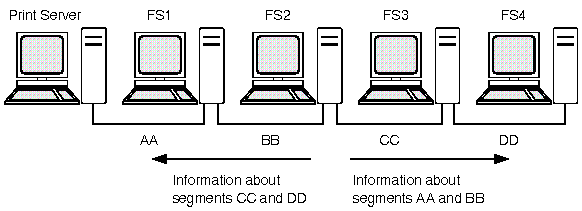
A router sends routing information broadcasts to every network segment to which it is directly connected, as illustrated in ``The best information algorithm''.
The best information algorithm
The purpose of routing information broadcasts is to:
The first rule of the best information algorithm dictates that a router about to broadcast to a particular network segment should not include any information about other segments that it has received from the particular network segment to which the information is being sent.
For example, if the router within server FS2 in ``The best information algorithm'' is going to broadcast routing information to network segment BB, it will not include information that it received from FS1 about network segment AA. If it did, someone on segment BB might erroneously conclude that there are two paths to segment AA, one through FSl and another through FS2.
The best information algorithm also states that routers should not include information about the network segment to which they are sending routing information broadcasts. For example, FS2 would not include information about BB in its broadcast to BB.
Taking these rules into account, the information that FS2 would broadcast to segment BB would be information about segments CC and DD.
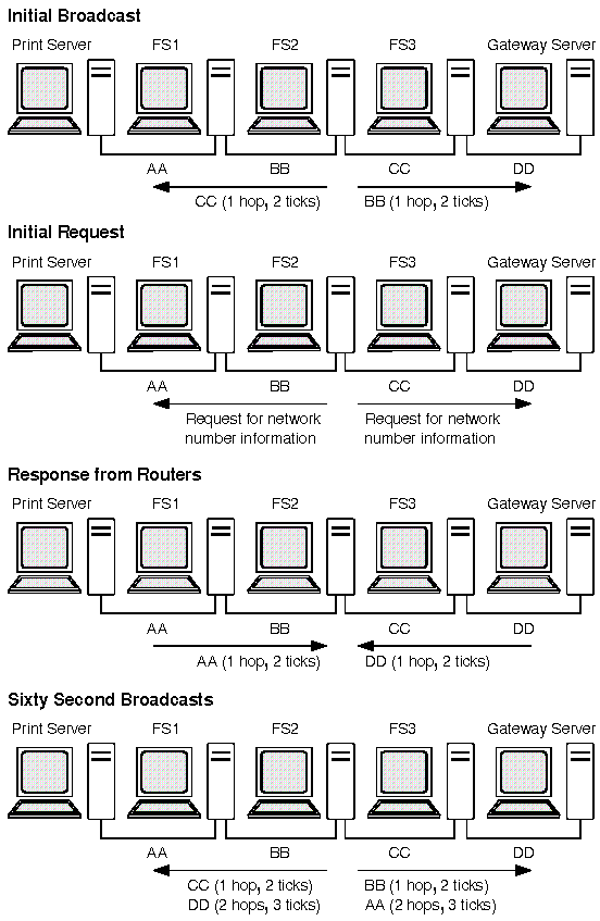
When a router is first brought up, it:
Sequence used to build and maintain the routing information table
Once the router has performed these initial broadcasts and updated its routing information table, it is ready to accept routing requests and route packets. In addition to routing packets, the routers will broadcast all the information in their routing information table (except that excluded by the best information algorithm) to each of their connected network segments every 60 seconds. Routers perform these periodic broadcasts to make sure that all routers on the network remain synchronized.
Because of the lower bandwidth of X.25 and asynchronous links, routers do not perform 60-second broadcasts on these links; only initial broadcasts, changed information broadcasts, and final broadcasts are sent over these links.
When a router receives information that causes it to change its routing information table, the router immediately passes that information on to its other directly connected network segments, except the segment from which the router received the information. If a new network segment comes up or an existing segment goes down, all the routers on the network will learn about the change in a short period of time.
The primary causes of a change in the network's configuration are file servers or external routers coming up or going down. If a router needs to be brought down, the router will inform its directly connected segments of the fact before discontinuing service. The router issues broadcasts, using the best information algorithm, that indicate that the network segments that the router had made available will no longer be accessible through this router.
If a router goes down due to a hardware failure, power glitch, or power outage, other routers will not be notified that a change has occurred. To safeguard against this eventuality, an ``aging'' mechanism has been built into NetWare routers.
Routers maintain a timer for each entry in their routing
information table.
Every time that information is received
concerning the entry, the timer is reset to zero.
If the timer
reaches three minutes, the router assumes that the route to the
network number is down and broadcasts that fact to its other
segments.
Because this information is new or changed, the routers
that receive the information will pass it on immediately and the
change will quickly permeate the network.